Home
Krohne Ifc 100 Wiring Diagram . Ifc 100 signal converter can be combined with any krohne flow sensor, making it very widely used. Current output output data volume flow, mass flow, diagnostic value, flow velocity, coil temperature, conductivity without hart� q = 0%:
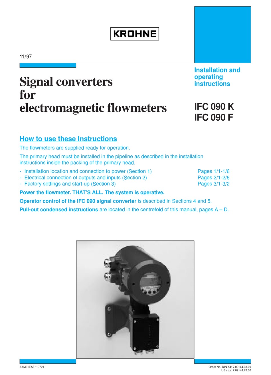
Krohne Ifc 090 K Installation And Operating Instructions Manual Pdf Download Manualslib from data2.manualslib.com Den v�tska som skall m�tas m�ste vara elektriskt ledande. The documentation is only complete when used in combination with the relevant documentation for the sensor. Signal converters ifc for optiflux series of emf, mac for optisens. Signal converter for electromagnetic flowmeters. Signal converter in wall version.
Krohne ifc 100 �r en signalomvandlare f�r induktiva fl�desm�tare. 1 stranded drain wire (1) for the inner shield (10), 1.0 mm2 cu / awg 17 (not. Den v�tska som skall m�tas m�ste vara elektriskt ledande. Connection diagram for signal and field current cable 1 electrical terminal compartment in the signal converter 2 signal cable a 3 field current cable c 4 electrical terminal compartment in the flow sensor 5 functional ground fe. F factory settings error during the crc check of the factory settings. Construction of signal cable a. Signal converter in wall version.
Source: img.yumpu.com Connection diagram for signal and field current cable. Ifc 100 kan anv�ndas tillsammans med en m�ngd olika typer av m�tr�r (givare). Ifc 100 ? lire en ligne ou t�l�charger en pdf ? krohne ifc 100 converter quickstart fr manuel d'utilisation.
The documentation is only complete when used in combination with the relevant documentation for the sensor. Ifc 100 ? lire en ligne ou t�l�charger en pdf ? krohne ifc 100 converter quickstart fr manuel d'utilisation. Signal converter for electromagnetic flowmeters.
85?250 vac, 24 vdc or 24 vdc/ac (4 wire). F factory settings error during the crc check of the factory settings. 1 stranded drain wire (1) for the inner shield (10), 1.0 mm2 cu / awg 17 (not.
Source: La pr�sente documentation n'est compl�te que si elle est utilis�e avec la documentation concernant le capteur de mesure. Diagnostic functions ifc 100/ifc 300. Connection diagram for signal and field current cable 1 electrical terminal compartment in the signal converter 2 signal cable a 3 field current cable c 4 electrical terminal compartment in the flow sensor 5 functional ground fe.
No message if empty pipe. Anleitungen und benutzerhandb�cher f�r krohne ifc 100. We have 1 krohne ifc100 manual available for free pdf download:
The krohne ifc signal converter will need to be setup to output pulses from the flow meter. We have 1 krohne ifc100 manual available for free pdf download: Consult krohne messtechnik's entire ifc 100 catalogue on directindustry.
Source: www.manualsdir.com The ifc signal converter manual? No message if empty pipe. Connection diagram for signal and field current cable.
Signal converter for electromagnetic flowmeters. Diagnostic functions ifc 100/ifc 300. The ifc electromagnetic flow converter for the food and beverage industry.
20?22 ma with hart� q. For further information refer to connection diagrams of outputs on page 39 and refer to technical data on page 77. The ifc 100 was designed for applications requiring an economical measuring solution with a high level of technology.
Source: For further information refer to connection diagrams of outputs on page 39 and refer to technical data on page 77. Anleitungen und benutzerhandb�cher f�r krohne ifc 100. La pr�sente documentation n'est compl�te que si elle est utilis�e avec la documentation concernant le capteur de mesure.
The documentation is only complete when used in combination with the relevant documentation for the sensor. The ifc signal converter manual? 4.5.2 connection diagram for signal and field current cable.
Krohne ifc 100 �r en signalomvandlare f�r induktiva fl�desm�tare. The krohne ifc signal converter will need to be setup to output pulses from the flow meter. The shielding must be connected in the housing of the 4 electrical connections.
Source: img.yumpu.com Ifc 100 kan monteras p� tre s�tt; Signal converter for electromagnetic flowmeters. 4.5.2 connection diagram for signal and field current cable.
4.5.2 connection diagram for signal and field current cable. We have 1 krohne ifc100 manual available for free pdf download: 85?250 vac, 24 vdc or 24 vdc/ac (4 wire).
The ifc signal converter manual? Complain wrong brand wrong model non readable. Connection diagram for signal and field current cable 1 electrical terminal compartment in the signal converter 2 signal cable a 3 field current cable c 4 electrical terminal compartment in the flow sensor 5 functional ground fe.
Source: img.directindustry.com Construction of signal cable a. 4.5.2 connection diagram for signal and field current cable. 1 stranded drain wire (1) for the inner shield (10), 1.0 mm2 cu / awg 17 (not.
Signal converter in wall version. Krohne ifc converter quickstart en user manual | 32 pages. Anleitungen und benutzerhandb�cher f�r krohne ifc 100.
Ifc 100 safety instructions 1. The krohne ifc signal converter will need to be setup to output pulses from the flow meter. Signal converters ifc for optiflux series of emf, mac for optisens.
Thank you for reading about Krohne Ifc 100 Wiring Diagram , I hope this article is useful. For more useful information visit https://thesparklingreviews.com/